If you want to make another calculation just click on the Reset button then re-enter the new values. Propeller shaft in a geared controllable pitch.
Drive Shaft Design Calculation For Automobile
The maximum torque that can be operated on the shaft T Max 207006 N-m.
. Single Member Report Export single member analysis reports in an easy and professional format to pass on to your client or fellow engineer. Twisting moment T 500 N-m 500 10 3 N-mm. 7614 mm Inner Diameter of section.
The given permissible shear stress for the shaft material is 40MPa. Axial Load F 10 kN 10 10 3 N. Local yield will normally not be a decisive criterion for marine shafts.
38205 mm Position of centroid -. The designing shall be done after determining all the input parameters. Permissible shear stress τ 40MPa 40 Nmm 2.
Design of propeller shaft Calculation for Moment of Inertia of propeller shaft. 6481 Area of section. A free body dia-gram of the shaft will allow the torque at any section to be determined.
This rotary force necessary to turn the shaft is simply torque. Dimensions of pre-existing propeller shaft of the car and using them for further calculation and analysis. 42 Design of propeller shaft.
The calculator utilizes the following industry accepted formula endorsed by. 207006 x 10 3 N-mm 70Mpa N-mm 2 x π x d 3 16. The propeller shaft is geared down by a ratio of 227.
The drive shaft also called propeller shaft or prop shaft is a component of the drive train in a vehicle with the purpose of delivering torque from the transmission to the differential which then transmits this torque to the wheels in order to move the vehicle. Bending moment M 1 kN-m 1000 10 3 N-mm. Most shafts will transmit torque through a portion of the shaft.
Typically the torque comes into the shaft at one gear and leaves the shaft at another gear. In this part of the automobile propeller shaft design calculation tutorial we will see the critical speed calculation procedure for the example problem. Where the engine and axles are separated from each other as on four-wheel drive and rear-wheel drive vehicles it is the propeller shaft that serves to transmit the drive force generated by the engine to the axles.
This free propeller shaft size calculator helps you determine the proper propeller shaft diameter for your boat. Torque Force length Nm Power Force Velocity Force length angular velocity. D 3 150687075 mm.
ShaftDesigner is a CAE shaft calculator software for high-quality marine propulsion fair curve shaft alignment bearing bush calculations torsional vibration analysis axial vibration analysis and whirling vibration analysis at the design production maintenance and ship repair stages. Perfect solution for the concept design checking before the final drawings production. These includes conventional as.
Calculate maximum static deflection of the driveshaft δ. Allowing you to solve more complex shafts with more loads bearings and stress concentrations. Design Analysis- FEA of Propeller Shaft Assembly.
Find bending moments from gears pulleys or sprockets that are transmitting loads to or from other devices. σA dynamic stress amplitude S safety factor U fatigue strength amplitude. Rps_prop frac7167227316 rps The advance ratio follows.
Virtual Product Development VPD is an approach that takes a design at the earliest concept stage and fully evaluates design specifications and usage scenarios and then uses this information to. Shaft horsepower is converted to a rotary force or moment applied to the propeller. Calculation of Bending Moment Effect.
The calculator determines a safety factor design coefficient based on shaft diameter max engine RPM shaft horsepower gear ratio and torsion strength of the shaft material used. The other symbols have the same meaning as in 222. Marine Propeller Shaft Calculations Propeller Shaft designing requires inputs such as engine power engine speed output power and speed range to be attained gearbox parameters etc.
1 Calculation example 1. Compare combined stresses to suitable allowable stresses. Static deflection is calculated from the equation.
The torque is often relatively constant at steady state operation. The drive shaft is primarily used to transfer torque between components that are separated by a distance since different. Designing involves finding diameter of the propeller shaft both tail shaft and intermediate shaft.
Determine torque in shafts from gears pulleys sprockets clutches and couplings. SECTION 2 CALCULATION OF HIGH CYCLE STRESSES IN PROPELLER BLADES 1 High cycle stress criterion Dynamic stress amplitudes in the propeller blade shall fulfil the following criterion. Factor whore value depending on the different constructional features of shafts is given below.
The criterion for this load case shall not be perceived as a design requirement versus static fracture or permanent distortion. From this maximum operating torque we can find the shaft diameter with the above equation. Design of Propeller Shaft Flanges Thickness of flange 025 d 5 027 x 500 T 140 mm Mass of flange excluding shaft 4 x dp2 d j 2 xtf xp dp 500 mm BENDING MOMENT CALCULATION For Propeller Shaft R aft R fwd 1471 x 4980 646293 155653 23537173 1 R fwd x 3040 64629334 x 431333 155653 x 66667 0 666671471 dx 0.
The shear stress due to the torsion. Calculate the propeller shaft Diameter. T Max 207006 N-m.
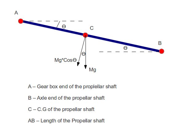
Outer Diameter of section. The stresses referred to are principal stresses. Bending moment occurs because of the own weight of the shaft.
128661 mm2 Position of centroid - X. 1 August 15 2007 1 17. D 5319 mm.
δ 5mgcos θ L3384EJ 0036579 mm. The minimum diameter of the propeller shaft is not to be less than the value dp in mm given by the. Calculation of shafts in marine applications.
A prop-shaft assembly consists of a propeller shaft a slip joint and one or more universal joints. Shaft Design Objectives Compute forces acting on shafts from gears pulleys and sprockets. You just need to enter the required values inside the brackets then click on the Calculate button to see the result.
The calculation goes as below. J fracVnd frac6173316times17 115. The bending moment must be calculated according to the.
- Selecting the feasible material for Propeller Drive Shaft for a car considering the required parameters. Used to rotate the shaft connected between the engine and the propeller.
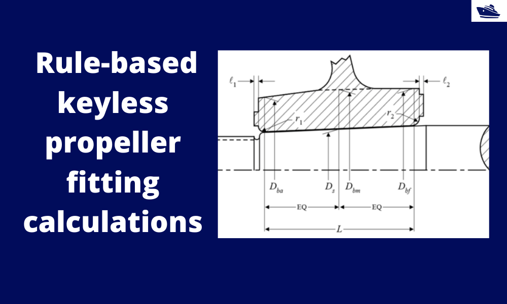
How To Do Rule Based Fitting Calculations Of A Keyless Propeller Thenavalarch

Propeller Shaft Design Software Skf Solution Factory Marine Services Calculation For Ships

Propeller Shaft And Drive Shaft Automobile

Propeller Shaft And Drive Shaft Automobile

Problem 1 On Design Of Shaft Design Of Machine Youtube
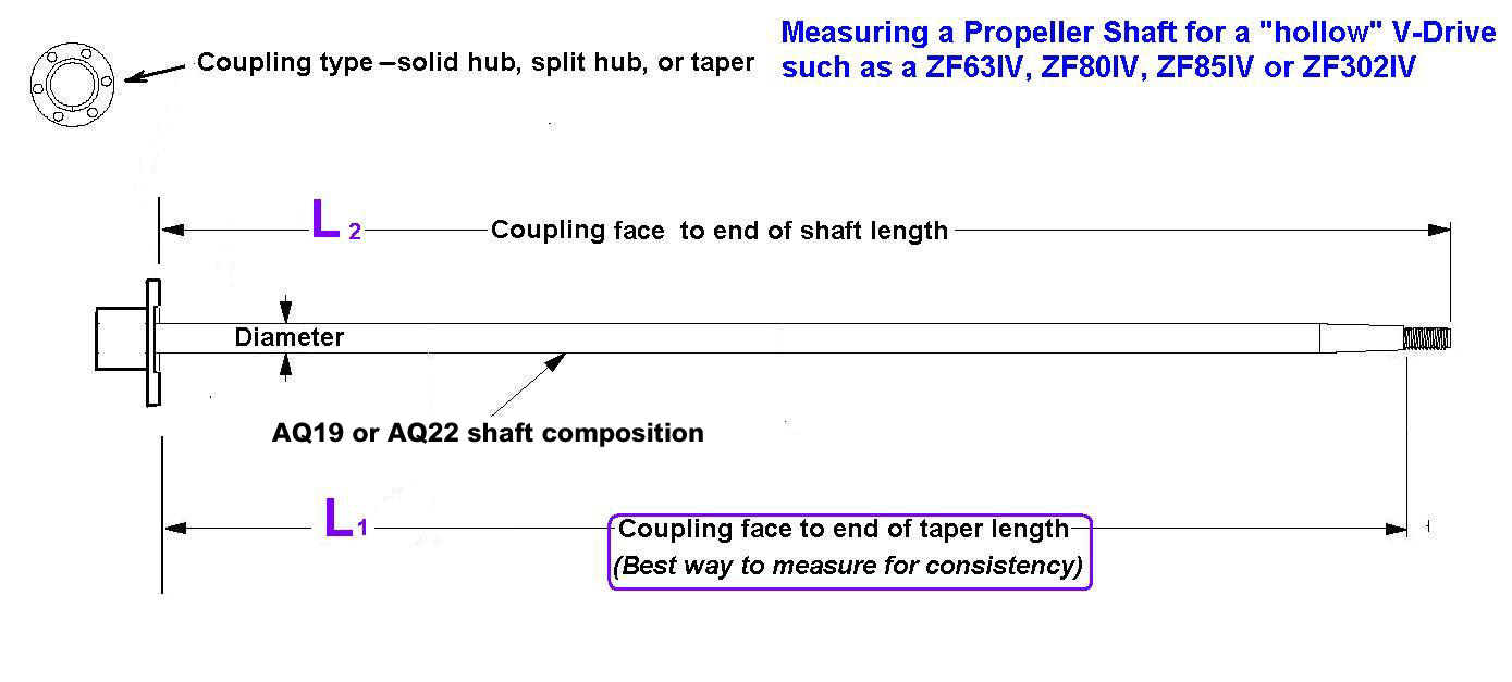
How To Measure The Propeller Shaft And Propeller Shaft Coupling Seaboard Marine

Propeller Shaft And Drive Shaft Automobile

Propeller Shaft And Drive Shaft Automobile
0 comments
Post a Comment